A flat roof may contain the correct insulation, a suitable waterproofing membrane and a high-performance air and vapour control layer (AVCL), yet still develop moisture problems. The weakness is often at the perimeter, around a rooflight or where a pipe, duct or cable crosses the construction. These are the places where a neat sequence of layers must become a real, buildable junction.
This guide explains how to trace the air-control and vapour-control functions through those details, what can interrupt them, and what to inspect before critical work is concealed. It concentrates on design principles rather than prescribing one membrane or manufacturer's detail. The related Roof Upstands guide addresses waterproofing height, terminations and rainwater paths; this article follows the hidden air and vapour-control line behind those weatherproofing details.
1. Airtightness, Vapour Control and Waterproofing Are Different Functions
Three functions must be distinguished. The air barrier limits unintended airflow through gaps, joints and interfaces in the building envelope. Vapour control limits water-vapour diffusion through materials in accordance with the moisture design. Waterproofing resists liquid water arriving from the outside. The functions may be provided by one material in a particular arrangement, but they must not be assumed to be identical. [1, 2, 8]
An AVCL is selected to provide an intended combination of air-tightness and vapour resistance. Its declared vapour resistance is only part of the story: unsealed laps or a gap beside a pipe can bypass the membrane. Conversely, a material or assembly may form a useful air barrier without having the vapour resistance required for a specific roof. The designation "airtightness membrane" describes the air function, not necessarily the complete vapour-control strategy.
The vapour-control layer should not be confused with a breather membrane, water-flow-reducing layer (WFRL) or the external roof covering. Each has a different job. The material properties and the chosen positions within the build-up must suit the thermal and hygrothermal assessment. [1, 2, 10, 11]
2. Why Small Gaps at Junctions Matter
Water vapour can reach a colder part of a roof by diffusion through materials, but it can also be carried by unintended air movement through openings. The second route is not reliably represented by a conventional one-dimensional vapour-diffusion calculation. BS EN ISO 13788 expressly identifies air movement through gaps as a phenomenon outside its simplified interstitial-condensation method. [10]
The consequences are not always an immediate drip. Moist air entering a colder part of the build-up may contribute to condensation, increased moisture content of insulation or timber, loss of thermal performance and conditions favourable to mould or material deterioration. A visible stain can also come from rainwater entry or trapped construction moisture. Symptoms alone cannot identify which transport mechanism is responsible. [2, 10, 11]
Parapets, rooflight kerbs and service penetrations deserve attention because they combine changes of material, geometry and responsibility. Membrane continuity is frequently interrupted by framing, fixings, fire protection, a new rooflight installation or another trade's later services. A specification that says only "seal all penetrations" does not explain how the seal is to be achieved.
3. Draw the Continuous Control Line Before Choosing a Tape
On a coordinated section, trace the primary air barrier from the roof field, across the junction and into the next air-barrier component. Draw the intended vapour-control line as well, noting where it coincides with the air barrier and where it does not. Then draw the exterior waterproofing and drainage routes separately. If one of these lines disappears at the parapet, kerb or service, the design is incomplete. [3, 8]
In a conventional warm-deck roof, an AVCL commonly sits above the structural deck and below the principal thermal insulation. In a cold-deck arrangement, the air/vapour-control strategy is normally on the room-warm side of the insulation; the ventilation strategy is a separate question. In an inverted roof, the waterproofing is below the insulation and may contribute to vapour control, but the air-barrier continuity and suitability of the complete assembly must still be established. These descriptions are examples, not universal layer schedules. [1, 2, 3]
The designer should identify the actual receiving surface. It might be a continuous plastered masonry inner leaf, concrete, an appropriate board joint system, a tested proprietary kerb, or a separate internal air-barrier membrane. Unplastered blockwork, open decking joints, rough render and a generic bead of sealant should not automatically be considered durable airtight substrates. The seal needs a defined support, suitable preparation and a specified connection method. [8, 9]
Finally, decide who installs and inspects each transition. The roofer may lay the AVCL; a façade contractor may finish the wall air barrier; a rooflight installer may fit the frame; mechanical and electrical trades may cut later openings. Without a coordinated handover, every trade can finish its own work while leaving a gap in the overall system.
4. Parapets and Roof-to-Wall Abutments
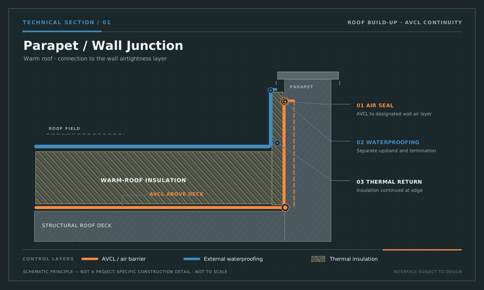
At a parapet, the roof AVCL must connect to the intended wall air-barrier system with an approved transition. The connection may turn up a prepared vertical surface or use a flexible transition membrane or compatible tape. The exact detail depends on the AVCL, wall construction, movement and receiving substrate. Do not simply stop the AVCL at the deck edge and assume the external waterproofing upstand has completed the internal air seal. [3, 8, 14]
The wall itself may contain several moisture-control components. A cavity tray or damp-proof course directs incidental water in the wall outward. A coping and flashing shed rain. The thermal insulation should continue as far as practical across the roof-to-wall transition to limit cold bridges. These components need coordination, but a cavity tray is not automatically the airtightness connection and an airtight seal must not obstruct designed drainage from the wall cavity. [6, 8, 14]
On refurbishment projects, a new layer of roof insulation can alter the relationship between the AVCL, wall insulation, existing damp-proof detailing and available upstand height. Where the wall air barrier is concealed, the contractor should not guess that a weathered outer wall surface is airtight. Expose or investigate enough to define the real connection. [1, 2]
What to show on the drawing: roof AVCL; receiving wall air barrier; actual transition and substrate; insulation continuity; movement allowance; waterproofing upstand and termination; coping, cavity-water path and drainage; access for inspecting the seal before covering.
Technical section 01 — Parapet/wall junction: the orange line represents a possible AVCL-to-wall airtightness transition; the dashed line is a conceptual continuation of the wall air barrier. Its real location must be confirmed for the building. The blue line represents the separate external waterproofing route. Neither line establishes a universal termination or upstand dimension.
5. Rooflights, Access Hatches and Raised Kerbs
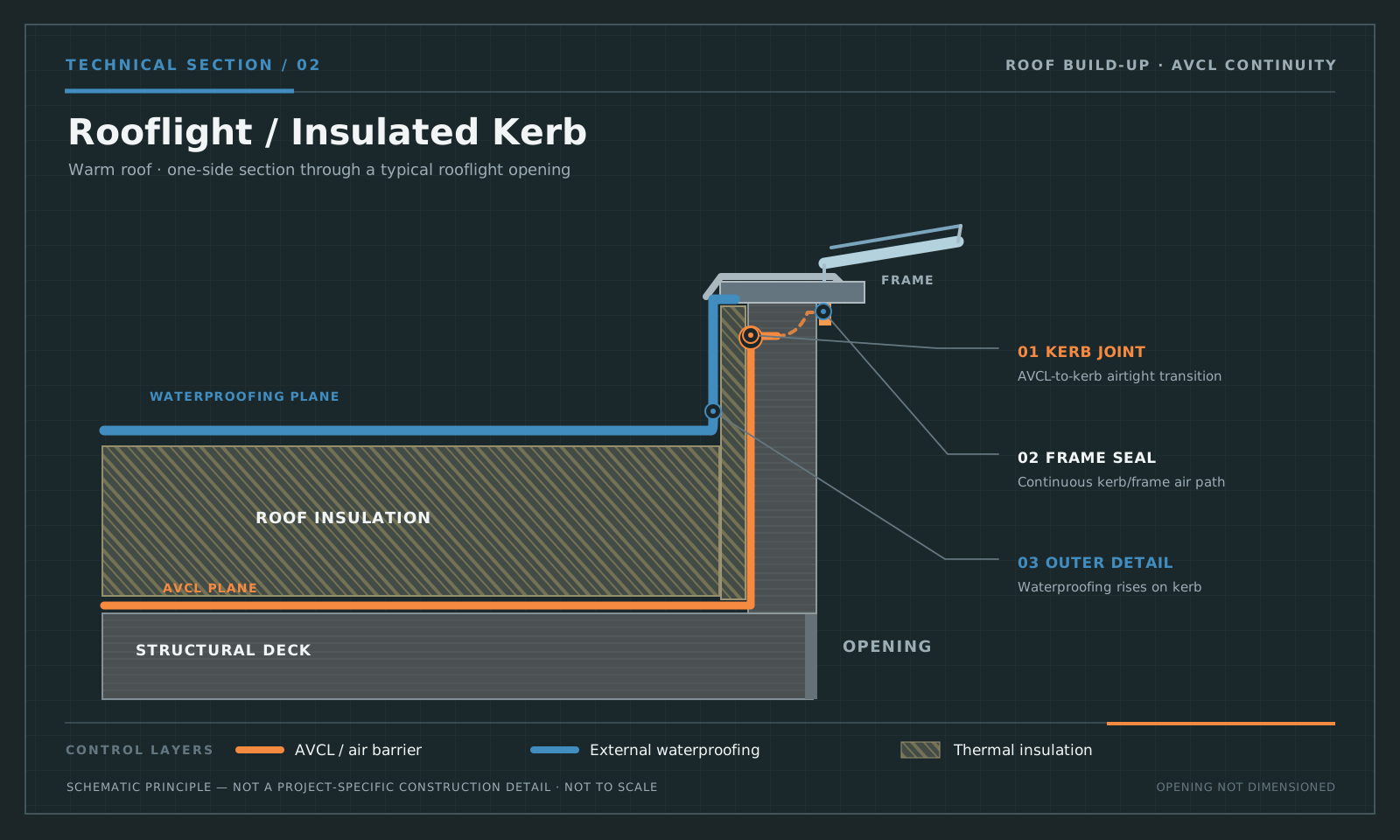
A rooflight introduces a framed opening, a kerb, changing surfaces and corners. A technically complete section needs two defensible routes: an inner air/vapour-control connection from the roof construction to the specified kerb or frame air-seal surface, and an outer weatherproofing connection that sheds rain and drains appropriately. They are distinct functions even if an approved proprietary detail links layers at a particular location. [3, 4]
The LRWA warm-roof rooflight example expressly shows a lap between the waterproofing system and AVCL. That drawing is marked as an indicative typical detail and directs the reader to the manufacturer's current system-specific requirements. It should not be copied literally into every rooflight arrangement or treated as proof that any two membranes can be bonded together. [4]
Check how the AVCL returns around the corners, where it bonds or mechanically seals, and whether the receiving kerb has a suitable air-control surface. The airtightness path must then continue across the specified kerb-to-frame connection, including corner seals: an isolated frame gasket is not, by itself, proof of a continuous path to the roof AVCL. A continuous bead around the visible frame does not necessarily seal the hidden joint between the kerb and roof structure. Insulation should meet the kerb without a significant cold bridge; the junction may require a project-specific condensation and surface-temperature review. Allow for differential movement and accessibility of seals without imposing tensile strain on tapes or membranes. [2, 8]
Preformed corner products can illustrate a manufacturer's approach to difficult junctions, but their stated application must be respected. For example, Eurovent describes CORNER PRO IN primarily for window and facade corners, with associated vapour-control membranes among its system products; this is not an automatic approval for a flat-roof rooflight kerb. [17]
When a rooflight is replaced, the old opening may contain discontinuous timber packing, damaged insulation or a redundant membrane line. Inspect these hidden elements before assuming a replacement unit will restore airtightness. The outer upstand weathering, its height and termination remain governed by the roof waterproofing design and are discussed in the separate Upstands article.
Technical section 02 — Rooflight/kerb junction: check the AVCL-to-kerb seal, the full kerb-to-frame air-seal route and the independent exterior waterproofing. The sketch illustrates these as separate inspection points; it does not verify any particular proprietary rooflight's seal design.
6. Pipes, Cables, Ducts and Other Services
Every penetration through the air barrier needs its own designed connection. For small round pipes or cables, appropriate proprietary grommets, collars or compatible tapes can provide a controlled seal when installed on a sound membrane with the specified preparation and overlap. Product instructions also address the need to avoid creases and tensile strain. Separate product details may be needed for single cables, cable groups and pipe sizes. A manufacturer's example is evidence for that product assembly, not permission to mix components from unrelated systems. [5, 9, 15, 16]
The problem becomes harder with bundled cables, irregular ducts, pipes subject to movement and services installed after the roof is closed. Grouping penetrations into a properly designed service zone or kerb can reduce the number of breaches through critical layers. Sleeves may simplify access, replacement and sealing, but both the sleeve-to-AVCL and service-to-sleeve interfaces need assessment. A loose opening filled only with general-purpose foam or a weathering collar that seals only the top membrane does not establish continuous air and vapour control.
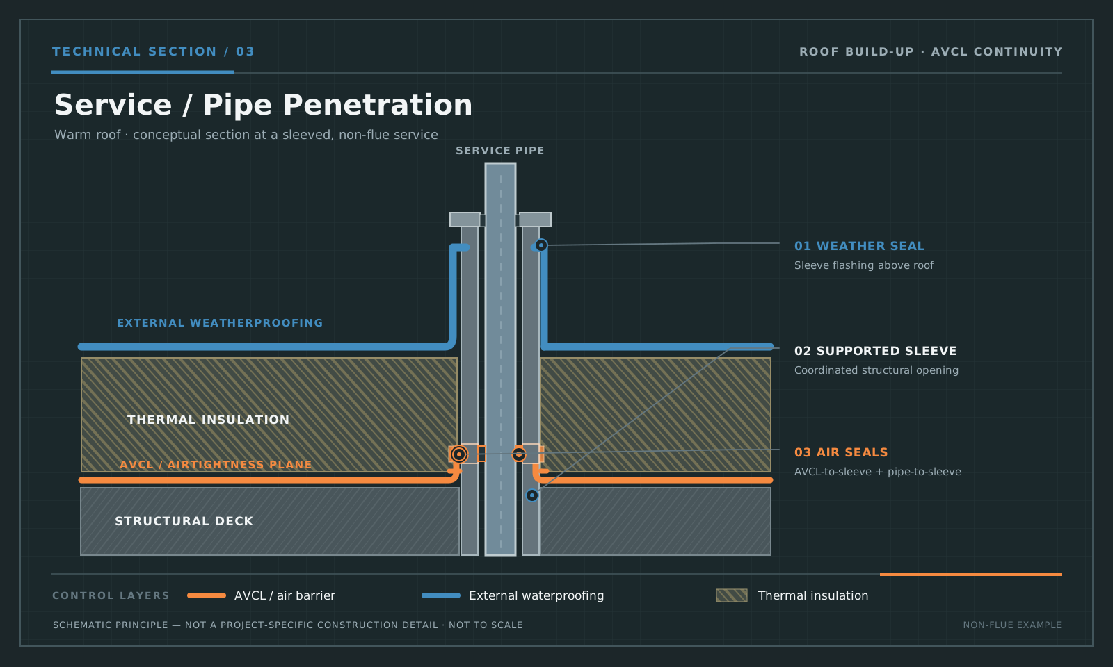
Where a sleeve is used, verify the two separate sealing interfaces at the air-control plane: (a) AVCL to sleeve and (b) sleeve to service pipe or cable. A watertight cap at roof level does not automatically seal the annular gap at AVCL level. The chosen detail must accommodate expected movement and service access without compromising the air barrier or any required fire-stopping arrangement.
Services involving heat, combustion products or fire-rated compartment lines need specific fire, temperature, movement and clearance design. A generic airtightness tape or collar must never be assumed suitable beside a flue or to provide fire stopping. The relevant building-services designer, fire design and proprietary tested assembly take priority. The Irish Technical Guidance Documents include Parts B and J among other applicable requirements. [13]
Two distinct questions must be answered at each penetration: (1) how is the air/vapour-control plane sealed at its own level, and (2) how is the outer waterproofing connected and weathered? The outer seal must be inspectable and compatible with the membrane system; the inner connection must not be left as an inaccessible guess. [3, 5]
Technical section 03 — Sleeved pipe penetration: show the AVCL-to-sleeve collar and a distinct annular seal between sleeve and pipe, both separate from the exterior weathering. The drawing uses a non-flue service solely to explain the control-plane principle; it is not suitable as a generic flue, fire-resistance or movement-joint detail.
7. Roof Outlets and Penetrations Through the Deck
Outlets are sometimes considered only as drainage components. In a warm roof they can also interrupt the AVCL and insulation. The LRWA typical sumped outlet detail identifies the need to coordinate laps between the AVCL and outlet and between the waterproofing and outlet. The flange, fixings, geometry and compatibility are system-dependent. [3]
The seal at the air-control plane cannot be inferred from the visible waterproofing flange alone. Nor should an AVCL detail obstruct drainage, trap incidental water in the wrong location, block inspection or interfere with the structural fixing of an outlet. Record where each control plane connects, including any sump insulation and the route for maintenance access. For inverted roofs, verify the relevant upper and membrane-level drainage arrangements separately.
8. Material Compatibility and Moisture Design
Choose an AVCL and its accessories using declared properties for the intended system: vapour resistance or equivalent vapour diffusion thickness (sd), air-barrier performance, lap/seam method, substrate adhesion, temperature and movement limits, and compatibility with insulation, primers, adhesives and waterproofing. A membrane with high nominal vapour resistance is not automatically a safe choice in every roof; the arrangement must also allow a suitable moisture-management and drying strategy. [1, 2]
Roof-specific self-adhesive AVCLs
For a warm-deck flat roof, the AVCL may be a purpose-designed self-adhesive bituminous membrane installed on a suitable structural deck before the insulation. Documented examples include DANOSA SELF-DAN AL PRO, an aluminium-composite-faced, self-adhesive SBS bitumen AVCL offered in 1.0 mm and 1.5 mm variants for roofs and cold stores, and Ravago RAVAPROOF STICKY VB 0.5 MM AL, an aluminium-faced, self-adhesive SBS-modified vapour-barrier membrane listed by Ravago for industrial warm flat-roof construction. These are examples of a membrane category, not an endorsement, a statement of interchangeability or approval for a particular deck, PIR board, primer or waterproofing system. [19, 20]
Product identity matters. Confirm the exact AVCL roll label, current technical datasheet, declared vapour resistance and proposed system before specification. For the self-adhesive AVCL, check the deck type and finish, dryness, primer requirements, laps, treatment at changes of plane, and protection during subsequent insulation installation. [19, 20]
Mechanically fixing PIR above an AVCL
Where PIR insulation is mechanically fastened through the AVCL into the structural deck, each fixing does penetrate the membrane. This does not necessarily mean the complete roof loses its designed vapour control: the SPRA Single Ply Roofing Design Guide explains that compression at properly installed fastener points has been found not to produce significant additional air/vapour permeability under the conditions addressed by its guidance. It is not a product-specific approval of every AVCL/fastener/PIR/deck combination or a guarantee that every screw hole seals itself. Check the roof-system and AVCL manufacturers' instructions, fixing specification, wind-uplift requirements and any unusual internal humidity. Fixings compressed beneath insulation are different from unsealed pipes, cables, sleeves or open construction joints. [3, 21]
Where there is unusual interior humidity, wet construction, retained roof layers, moisture-sensitive timber or an uncertain retrofit build-up, the designer should determine what hygrothermal assessment is appropriate. BS EN ISO 13788 provides a simplified diffusion-based method within stated limitations; BS EN 15026:2023 concerns transient heat-and-moisture simulation. Neither calculation excuses unsealed construction gaps. [2, 10, 11]
Adhesive connections deserve particular attention. A tape that works well on a clean proprietary sheet may fail to bond to dusty or damp masonry without the required primer, levelling or substrate treatment. A mechanically supported transition or approved liquid-applied connection may be more appropriate in some geometries, but its suitability must be documented for that exact system. Do not substitute a manufacturer's unrelated airtightness product for a tested roof AVCL detail without verification. [3, 9, 18]
9. New Work and Refurbishment Present Different Risks
On new work, the opportunity is to sequence interfaces before they become hidden. Show in the roof package what the wall contractor must leave ready, how kerbs and service sleeves are to be installed, and at what point the roofer can seal and photograph the AVCL. The design should make realistic allowance for access, tolerances and movement.
On refurbishment, a flat roof may retain insulation, layers and details whose continuity cannot be established visually from the top surface. An overlay can conceal an existing broken air-control line. Survey information should cover the roof construction, internal humidity conditions, visible defects, previous leak history and intrusive checks where appropriate. Where the existing AVCL is missing, degraded or inaccessible, a new detail may need more than a local tape repair. [1, 2]
A local thermal image, damp meter or staining pattern may suggest where to investigate; it does not, by itself, prove whether moisture came from diffusion, air leakage, liquid water penetration or construction moisture. Recording uncertainty is part of a competent investigation.
10. Verification Before the Layers Are Concealed
Quality control is most useful while the AVCL is still visible. Inspecting only the finished waterproofing may show a weather-tight surface while missing breaks underneath. For each junction, retain an approved marked-up drawing and photographs that show the membrane, receiving surface, laps, corners, collars and finished sealed connection before insulation or lining covers it.
Where appropriate, building or zone pressurisation testing can help evaluate overall air permeability and assist in finding leakage locations. ISO 9972:2015 describes the fan-pressurisation measurement of buildings or parts of buildings; it does not assess individual components by itself. Smoke visualisation or targeted leakage investigation may be useful under controlled test conditions. These tests do not replace material compatibility checks, condensation assessment or waterproofing integrity testing. [12]
An electronic leak-detection test or flood test of the external roof membrane addresses a different question from AVCL continuity. Passing one does not establish that the other control line is sound. Testing methods and timing should be selected by competent persons for the actual roof and its construction stage.
11. Typical Defects and the Follow-Up Question
| Observed detail | Why it matters | What should be checked |
|---|---|---|
| AVCL stops at the roof deck edge | No defined route to the wall air barrier | Approved roof-to-wall transition, substrate and responsibility |
| Membrane laps appear unsealed | Air leakage can bypass stated sheet properties | Specified lap treatment, adhesion and continuity |
| Rooflight kerb is insulated but the inner joint is open | Possible air bypass and local surface cooling | Air-seal line, corner details and thermal connection |
| Pipe collar seals only the top membrane | Weatherproofing does not prove AVCL continuity | Both AVCL-to-sleeve and sleeve-to-service seals, where sleeved |
| Tape bridges dusty or moving construction | Seal may lose adhesion or be strained | Primer, surface preparation, support and movement allowance |
| New cable opening appears after inspection | A previously continuous plane has been breached | Reinspection and a documented compatible repair |
| Drawing calls every green film an AVCL | Material role and location may be misunderstood | Product identification, declared properties and roof design |
These observations are prompts to investigate, not automatic diagnoses of a failed roof. A photograph of a gap may prove discontinuity, but a moisture stain alone does not prove its source.
12. The Question to Ask Before Approving the Detail
Can the primary air-barrier line be followed continuously, in an actual buildable section, from the roof field into the parapet, rooflight kerb or service penetration? Can the designer explain whether that line also performs the vapour-control function, where its moisture resistance comes from, how it is connected and how it will be inspected? Can the exterior waterproofing and drainage route be traced separately?
If those answers depend on a trade "sealing it on site" without a compatible, specified transition and a moment for inspection, the detail is not yet ready to be covered.
The principle: trace the line, specify the connection, and verify it before it disappears.
Technical References
The sources below were checked on 23 October 2026. Standards publisher listings verify the current title, edition and published scope, but do not constitute a reading of every clause of the paid standard. Product guidance is cited only for the documented application; it is not a brand recommendation.
[2] BSI, BS 5250:2021, Management of moisture in buildings, code of practice.
[4] LRWA, Typical Warm Roof Installation, Rooflight or Access Hatch, indicative drawing, 2020.
[5] LRWA, Typical Warm Roof Installation, Pipe Penetration, indicative drawing, 2020.
[6] Government of Ireland, TGD L, Conservation of Fuel and Energy, Dwellings, current 2022 edition.
[7] Government of Ireland, TGD L, Buildings other than Dwellings, 2022 edition.
[11] BSI, BS EN 15026:2023, assessment of moisture transfer by numerical simulation.
[12] ISO, ISO 9972:2015, Determination of air permeability of buildings, fan-pressurisation method.